Blog 5th Nov 2018 – Small Power Supplies using an 18650 battery As I’ve been working through the design of a stand alone processing unit with a PIC32MX170 CPU which uses a 2.4Ghz transceiver (based around the NRF24L01 chip) and a Digole 3.2” colour touch screen display. An early query was what power supply to use – given the device must be mobile. An attractive battery is a Lithium Ion 18650, given the amount of current it is capable of supplying. The downside is that directly powering logic from a single 18650 means the voltage will vary from around 4.2v when fully charged to as low as 2.5v when close to full discharge. The CPU will cope fairly well with this level of variation but the colour display becomes noticeably dimmer. I’ve used a CH340G chip in the design to permit USB communications with a PC – mainly because it presents a standard COM port signature for the PC to link to – and so makes establishing communications relatively easy. A USB plug connected to the socket will supply data and a 5v rail. The CH340G can actually use a 3.3v or a 5v supply and when using 5v rather handily outputs a low current 3.3v rail rated at around 30mA... enough to power the CPU but not quite enough to power everything else. During the development of the software – a 5v USB cable was connected and the 5v rail fed to a 3.3v regulator to supply everything else, but for a stand alone prototype... a better option was required.  
DD06CVSA Charging Board
One solution makes use of one of the rather large number of cheap step-up boards you can buy now – such as the DD06CVSA. This simple (and quite small) board has a 5v input for charging and two pins to allow the connection of a single 18650 battery. Another two pins supply the output – which is guaranteed to be 5v until the battery goes flat, at which point the board turns off. The onboard chip deals with management of the charge/discharge cycle while also protecting the 18650 battery. The PCB includes four dazzlingly bright LEDs that show the battery status (time to discharge and flashing to show charge time). Lastly the board has a "key" input which when taken low turns the board either on or off.
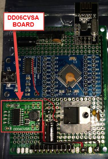
You can see the board highlighted in red on this prototype. During tests I found the output was a little noisy with around 140mV supperimposed on the 5v output rail. That was suppressed (below 20mV) by fitting a 0.1uF decoupler and a 47uF electrolytic close to the output. In use charge and discharge works well, but the board does have some quirks when switching on or off. If for example you have a USB cable plugged in, the board will be in charging mode and will output 5v to the rest of the system. Unplugging the USB cable with a fully charged battery would (I would have thought) leave the board outputing 5v, but inexplicably the board simply turns off. In addition the operation of the "key" input is unreliable especially if an attempt is made to turn the device on after a period of being off (overnight). Sometimes it powers up, sometimes you have to keep switching the key input to get it live. The board does automatically switch on if a load greater than around 50mA is presented and so in this case simply switching the load is the route I took to obtain reliable operation.
Display Unit Prototype showing CPU and Power board
There will be a better solution out there... one that ideally permits the CPU to fully control power cycling and at the same time query the battery condition. In this way the CPU can properly manage state while also managing the users expectation of use. But as it is, this isn’t a bad solution for a prototype - as shown below. Note the power LED's on the left side. Display Unit Prototype In this configuration with a PIC32MX 170 CPU running at 40Mhz, with an SPI NRF24L01 2.4Ghz comms transceiver running polling commands to a nearby device - and with the colour display permanently backlit and working - a single fully charged 18650 battery will power the system for over 8 hours. Comment | Back to Quick Links...