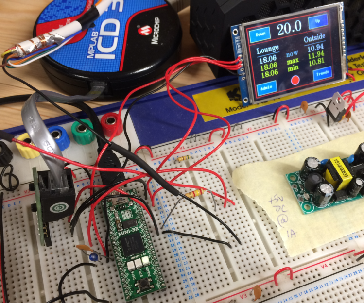
The picture shows the basic development platform - using breadboard fitted with a MINI-32 processor board, Digole colour display and wiring
required to connect the CPU to the 1-Wire bus. I coded the software so the display shows the target temperature (20) but with a means to alter in
0.5 degree increments. Temperature samples are taken by the system every minute from the lounge (main living area) and the outside of the house. When
there are more than three samples available the display will show the max and min of both. If the number of samples exceeds 60 (ie: 1 hour) then the
user can click the trends button to see a graph of what is going on... and that will be over the last 24 hours if there happens to be a full set of 1440
samples. The LED looking display (bottom centre) is an indicator of what the boiler is being told to do but I think I'll probably ditch that and instead
use a tricolour LED fitted to the front of the enclosure showing blue when the boiler is off, red when switched on and otherwise green when the system
is starting or off altogether.
The sharp eye'd out there may spot a lone voltage reg (a 5 to 3.3v) and nearby a 5V switch mode PSU. I'll be assessing that later with a mind to powering
the box as I'm not keen on using a capacitive power supply :-).
I'm also toying with the idea of interfacing the system with an ESP8266 chip to provide WiFi access as I quite like the idea of recording temperatures
accurately over many months - via an application running on a PC in the house connecting over TCP to transfer all temperature data continuously.