Blog 25th September 2024 Mains monitor I built the mains monitor board earlier today, consisting of an ESP32 (WROOM) board with a BUCK style PSU (mains in and 5v regulated DC out). I made a point of testing the small PSU on the bench for 24 hours just in case it went up in flames as I've found the QA can be a little bit hit and miss. Speaking of QA much the same applies with the ESP32 and ESP8266 boards. I've bought 24 of these boards (12 of each) and two were dead on arrival. Both were manufactured with layout faults of some of the surface mounted components. One had a three pin device rotated through 60 degrees which was easily repairable (at which point the board worked). Another had a nasty solder problem under the 2102 USB interface chip which I couldn't resolve. The board basically worked but no comms were possible. If I was a betting man, I'd bet that these clone boards don't get tested at all after manufacture. So, a long soak test under controlled conditions becomes pretty much essential. Note the red arrow showing the ESP32's 2.4Ghz antenna and the two pin jumper at the bottom left, providing a means to disconnect the +5v rail from the Buck PSU if/when I need to use the USB interface. Mains monitor PCB
The next step was to cut out an apperture for the antenna on the ESP32 PCB to allow it to protrude properly from the diecast box. I also had to deal with all the other various drillings in that box (for the earth M6 bolts, the two grommets, one large for the mains cable and a smaller one for the CT cable, the screws for the 10mm plastic 
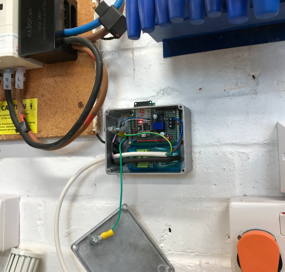
insulated stand offs supporting the ESP32 PCB and also a hole in the lid to ensure earthing continuity throughout the entire enclosure. You can see an orange mains plug which is used to feed live and neutal to the monitor board (and which is fused with the smallest fuse I could get). Also if you look at the consumer board you'll spot the CT clamp around the neutral tail heading out of the Henley box. The design provides a reasonable degree of safety given the mains is physically issolated from the low voltage component - actually in two ways. The PZEM board is encased and insulated. The mains wiring entering the choc block for that board is properly terminated with insulation up-to-but-not-touching the screw clamps. Regarding the prototyping PCB, this has a number of rows of disconnected 0.1" pitch, sitting between the ESP32 and Buck board. I also fitted a 2nd plate of 2mm thick plastic immediately under the buck board to act as an additional insulator (you can see that on the top picture). Low voltage wiring and high voltage wiring is double insulated where it crosses and the entire enclosure (including lid) is earthed. This last point is important, as technically this is a class 1 device which must have CPC continuity to the enclosure. The one remaining part to source is a clear plastic rectangular cap to sit on top of the ESP32 antenna - first and foremost to keep dust out but secondly to insulate even that low voltage part of the board, just in case anything did go horribly wrong. I'll need to play with that to make sure I don't end up compromising signal strength which is why, for now, I've left it off. Note that the box is physically remote from the consumer unit. All communications occur over the air.
Mains monitor fitted to the wall
Mains monitoring data
...and with around 6 nodes in the MESH (including the mains monitor node) reliable comms were established. Note that at this time, we were actually using the cooker (inductive hob and electric ovens) and so the current consumption accurately reflects that fact. (All node address values are aliased anyway - so the address shown can be ignored).
I'm pleasantly surprised by a power factor of 1.0, suggesting that the inductive and capacitive loads are fairly well balanced, even under relatively heavy load. Over time you can definately observe changes in voltage and frequency although the next step would be to graph that data to see how it behaves, perhaps over a day or maybe even a week as I'd imagine there may well be patterns to how these values will alter. Before I can do any of that, I'll need to setup a working MESH of ESP32's around the house, as right now they are placed rather hapazardly and one or two are using small USB battery supplies (for example a single 18650 USB charger pack will feed a working MESH'd ESP32 for around 18 hours). Longer term, what will be interesting will be to find out as/when the grid voltage drops off significantly. Comment | Back to Quick Links...