Blog 21st March 2024 Expressif anyone? Over the last couple of months I've been playing with Teensy boards employing IMXRT1062DVJ6 processors (ARM cortex M7 core) after my old mate Brian suggested it'd be well worth a look. Teensy is a creation of a rather smart chap Paul Stoffregen - and creation is the key word here. Popping a chip on a board arguably isn't that hard but building a well designed PCB with regulation, breakout pins, USB and peripheral support for an SD reader and Ethernet plus all the software support required to drive the board is much harder. Fortunately for us, he did and selected the Arduino framework as a starting point. I suspect a motivation for the board may have been the creation of music and driving visual effects hardware, which makes sense as soon as you scope the cycle times of this processor clocked at 600Mhz (and often overclocked with the right cooling and some coded precautions to prevent overheating). I've used Microchip PIC32MX chips for years, clocked at 40 or maybe 80Mhz and so all the more relished seeing this 600Mhz processor generating continuous GPIO writes with 4nS cycle times. The device is so quick my humble 40Mhz Kikusui scope couldn't even see logic transitions. Couple this board with a cheap touch screen display - for example a 320x240 board using an ILI9341 controller and you have a very powerful base for just about any embedded project you like. There were a couple of hoops I wanted to jump through as I worked on this Teensy board - given I've normally developed embedded hardware using the Microchip Integrated Development Environment (IDE) with either C or in years gone by, page banked assembler (where flying off into hyperspace was always a distinct possibility). This time I wanted to use the Arduino platform and in particular develop the project in C++, a language I'd never used before. hmmmm C++... for every person I've met who swears by it, I've met another who hates it with a passion. Personally, I've always found myself in two minds about the language. Polymorphism (think in terms of overloading functions that essentially do the same thing with different arguments for example add(1,2)=3 and add("coff","ee")="coffee") and encapsulation (where we place limits on precisely what can be changed, by how much and by who) tick all the right boxes when it comes to making good provable code that can be properly maintained. But being honest I've rarely encountered a real world example of inheritance that didn't require fairly horrible contortions, a lot of swearing and shoehorning to make sense.
Object Orientated Programming - Stack/Vector bad example of inheritance
Here we declare an object called Stack that extends Vector and can add functionality over and above what Vector provides. But the problem here is that a stack isn't a vector. As stack in this arrangement inherits existing Vector functionality, you'll then be free to add or remove elements at any place in the stack. You see the problem? Inheritance has allowed you to use a stack improperly. A Stack or first-in-last-out memory should only ever permit two operations that add/remove data, namely PUSH (to add new data) and POP (to remove data). Anything else means it is NOT a stack.
This example cited by Jeff Meunier is also worthy of note as it captures very poor use of inheritance. Meunier was reviewing java books in which one author cited the code shown as a really good use of inheritance. In particular the Circle class inherits the Points class translate method which means that translating a circle is the same as translating a point - all good stuff, right? Well, not really... because the line public class Circle extends Point actually means that all circles are a point, which is obviously not true. A circle is a collection of infinite points by virtue of its radius and as Meunier rightly says, "It requires a lot of mental gymnastics to even begin to reconcile the inconsistencies between this model and reality. The coding might be “correct”  —  the program runs just as the programmer wanted  —  but the model is very wrong".
Bad example of inheritance
There is a general principle in object orientated design known as the Liskov substitution principle - which asserts that it should always be possible to use a child object as a replacement for a parent object. In our example above, a circle object clearly can't be substituted by a point - oh dear.
Squares and Rectangles
Forgive another shape example, but this one is routinely cited as a good exemplar of poor inheritance involving squares inheriting from rectangles. This example gets debated, a lot. I've read folks respond in forums in all sorts of ways but my favourite challenge was "I have yet to see a square that wasn't a rectangle. Can you draw me one?". An excellent question, but one that manages to entirely miss the crux of the problem. If you think about it, a square is a special type of rectangle (just one where the width and height are the same). But the problems begin when you consider the two shapes, specifically from a programmers perspective. A rectangle needs two descriptive arguments while a square only needs one. You 
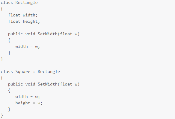
can freely change the width of a rectangle and it still remains a rectangle, but if you were to change the width of a square (without altering the height) then it would stop being a square. So the SetWidth-Method in our Square class can't be correct, because if it alters only the width you'll have a Square that isn't square. If it changes both the width and the height, then it isn't doing what the base version of the method does, which means the Liskov substitution principle is violated. Leaving aside these more abstract issues, it is also visually ugly, given the readability of a SetWidth method in a square class is logically inconsistent with the shape. I'd read this as a programmer and immediately feel uneasy. What other logical flaws am I about to walk into?
Leaving those issues to one side, object orientated languages generally all include encapsulation. If the class interface extended out publically is tightly controlled by data type then we have a strong contract between two parties (the class and the consumer of the class) which in my humble experience leads to robust, readable and maintainable code. The rest I can live with, given inheritance is a feature that can be used sparingly and sometimes avoided altogether. So I began this journey using C++ in the Arduino IDE and set about building a fairly good sized hello world project - utilising a suite of classes that would allow me to run a Teensy 4.1 coupled with either of two different displays (a Digole using fast UART comms or an ILI9341 based display using SPI - or even both boards simultaneously). It's not really a hello world project, it's more like a shell project that can be used as a basic template for future designs. At the subtle end of things, I explored the use of timers embedded in classes, using callbacks to drive regular 1mS clocks for various timing applications as virtually every embedded project I've ever built has needed that type of control. Using classes for these kind of tasks can be a useful way of tidying and removing clutter from setup() and main() because instead of having a load of code to create, setup and kickstart the timer hardware - you might instead see a single line along the lines of SystemTimer.begin(); but where the new timer class you've created encapsulates all the code required to deal with the hardware. Interestingly as hardware is generally a limited resource, then these types of classes often have to be single instance or Singleton types. They generally have to defend against multiple instances being created - so some care is required during development. The process gave me good insights into how C++ works. It also gave me a chance to explore the standard library, which is actually pretty good (I used deque lists in the ESP32 packet processing below - and found them to be very useful and robust). But by the time I was part way through, I could almost hear the little Arduino IDE groaning under the weight of it all. I'm using the version 2 Arduino IDE which in truth is pretty good at what it does... and importantly suits those who don't want to get bogged down with a lot of bells and whistles. You're free to code in either C or C++ and can even (sort of) split projects using multiple tabs (one per file). The library and board managers built into the IDE do an elegant job of opening a complex world of support and making it seem easy. But this IDE doesn't cope overly well if you want to develop and test more complex projects, sometimes involving dozens of classes and even multiple developers. The IDE has no understanding of repositories such as github, so the process of taking snapshots can be fairly long winded and manual. Also the IDE doesn't provide simple, easy to use project navigation to see the complete design. After creating a number of projects to scope out the limits of the Arduino IDE, I started looking elsewhere for something better. An alternate IDE I tried first and have stuck with now for nearly 3 months is the free version of Microsoft Visual Studio 2022 (actually version 17.5.2) along with a paid-for plug in called Visual Micro (the cost is very reasonable so don't let that put you off. I'd add that I needed to contact support once (after rebuilding my PC and running into a re-licensing issue) and they were absolutely superb). Using this combination is relatively simple - but does require some structure before you can start. Broadly speaking...
  • 1. Install the Arduino IDE. With this configuration you can use any recent IDE - my starting point was 2.0. Make sure this is working ok before proceeding
  • 2. Download and install Microsoft Visual Studio - Community Edition (which is free)
  • 3. Download and install an extension plug in called Visual Micro (note that you can try this without restriction for a period of time with no cost)
With this up and running you can create a project in visual studio and use the visual micro plug in to set the board, the libraries required and to compile. In fact Visual Studio via Visual Micro uses all the same tool chains built into the Arduino framework to compile the project so the two are very closely linked. With Visual Studio closed, you can even use the library and board managers in Arduino to download new devices and libraries safe in the knowledge that all of that will come straight across to projects you later open in Visual Studio. Using this new IDE I set about rewriting all my existing code - compiling and running to test and also updating github with repository backups and have been using it ever since. It works really well, feels far more robust and generally eases the burden of working on more complex projects. I heartily recommend it.
ESP32 boards MESHing ESP8266 or ESP32 With a viable IDE sorted out, my next project was to explore Expressif comms boards with a particular motivation in mind. I don't want to get into the politics of net zero... which in my view is unnecessary, unworkable nonsense, but I'm pretty sure the way this is being mismanaged now by the lunatics in office, means the grid is likely to stop working or be time limited in the future. So being able to monitor our house supply (voltage, frequency, current load, power consumed across time and power factor) may be quite useful and as it turns out, relatively easy using a PZEM-004T-100A board (see above pic - where the board is in the light blue plastic container). This board uses a CT clamp on the neutral line with a second direct low current connection to both line and neutral. With mains connected, the board sensor powers up and starts work. It can be queried via a UART serial interface employing opto-isolators on both the Rx and Tx lines for proper mains isolation (it is for this reason that you need mains on one side of this board and +5v on the USB side before the board will even switch on). A word of warning when using PZEM-004T-100A boards.
PZEM-004T-100A boards use a capacitive power supply - which we've already encountered further down in this blog when my central heating Honeywell ST9400C timer died. There are two issues with these capacitive PSU's to remember. Firstly when connected and running, some of the PCB will be live (ie: at mains potential). Secondly, unless the circuit is designed to discharge the capacitor when turned off, there is always the possibility of live voltages remaining on the PCB for some time after mains has been disconnected. So build defensively. I'd aim to put this into an earthed diecast box, where the PZEM-004T-100A is itself encased in its own plastic insulated case and physically separated from any other hardware. I specifically avoided buying a bare PZEM-004T-100A board that didn't have an insulated surround (see pic, actually from Amazon). CT loops generate significant voltages from their inductive coupling. In fact, on three phase installations those voltages can easily kill the unwary, so great care is required.
Uninsulated PZEM-004T-100A - be VERY careful
...and whatever you do please ignore the technically illiterate folks on youtube who advocate placing these types of IOT devices inside consumer units (ie: distribution boards). One of the most worrying examples of this particular brand of recklessness comes from a youtube account known as Electrical Projects (CreativeLab) with 106K subscribers. Note the comments, as it is clear that more than a few think this individual has done something to be applauded. Some of these comments build on the insanity (making it worse, if that's possible) such as the gem "it would have been nice to power your ESP from the line side of your main (sic) so it stayed on all the time". For me, the only comment that got close to the truth was "This creation is a fire hazard, life risk and over all a good idea with the worst execution possible". The video demonstrates negligible electrical knowledge and no grasp whatsoever of safety. Some of the really eye rolling low points are the use of a plastic case, using heat glue or silicon (of all things) to mount objects, mixing low and high voltage with no physical separation, the almost comically insane RCD trip mechanism he er... invented (obvs never heard of a shunt trip or even a contactor), using soldered inline heatshrunk fuses that carry mains, the horrible termination(s) all with exposed copper, his comically bad DIY breaker bus (consisting of clearly underspecified looped wire) and soldered wire used in clamped connectors. Jeepers, where the hell does one even start with something this bad? There is some truth to the old saying, just because you can do something doesn't mean you should. A UK home insurance policy would be invalidated as soon as this appalling bodge came to light and in the UK he'd be wide open to prosecution (given he clearly can't be a part P contractor). He may not be UK based... I'd like to pray really hard that he isn't. Bottom line is that home owners shouldn't be opening or going anywhere near a consumer unit without experienced qualified advice from a professional electrician. There is after all, a very good reason why it is so arduous and expensive to become one of those smart folks. Don't do this!!! My house isn't huge and while monitoring our consumer unit might be fairly easy with this board, communicating the monitoring data to my office (for example) is a nonstarter. The distance and the number of walls between the two boards means a pair of NRF24L01's, ESP8266's or ESP32 boards simply wont work. So point-to-point communications won't work over this distance but what if we added intermediate boards to act as relays? This is effectively what a MESH is. ESP boards have a freely available Arduino library known as PainlessMESH providing this facility in a fairly *coughs* painless way and which will work with ESP8266's or ESP32's. With painless mesh we can create a network of ESP32 and/or ESP8266 boards that self organise into a network and allow point to point communications via any of the intermediate nodes. In a house environment you might have one board in every room - and that coverage would mean you'd be able to send a packet from any one board to any other board even if that meant the packet had to traverse multiple nodes to reach the destination. Painless mesh doesn't tackle everything... for example yes you can initiate point to point communications to a specifically addressed node, but you'll have no idea if that communications data actually arrives, because the MESH doesn't deal with acknowledgments. You have to code that feature in the application layer. Another issue I found involves latency in operation. The MESH syncs clocks between nodes which is good... but appears to be very slow. So sending/receiving packets randomly without any specific time requirement will work just fine... but if you did want something to happen right now across boards in the MESH the process will be far more involved. A good example would be to have say 10 boards in a mesh and have them flash their on-board LED's at the same time, using commands issued by one of the 10 boards. Doable, but it isn't as easy as you might imagine. I've run a 16 board mesh here at the house with both ESP8266 and ESP32 boards. My implementation used application layer ACK's on all packets and where each packet had a type that could initiate a command or a reply to a command. It worked like a charm and I hammered it over around a week nonstop and couldn't get it to fall over at all. I've had so much fun exploring this I suspect I'll revisit this blog post in the future. Comment | Back to Quick Links...