Blog 23rd July 2022 Addendum to mass air flow woes You can read the potted history of my original fault further down in my blog - it linked to a faulty mass air flow (MAF) sensor for my 14CUX fuel injection system - one that I diagnosed incorrectly but fixed after biting the bullet and buying a new part. The part number in question is ERR5198P. The original MAF part fitted to the vehicle was stamped with the part number ESR1057 (it also had “5AM” written on the top). In fact this part is interchangeably replaced in the early 90’s by ESR1057L and in later years both parts were superseded by part number ERR5198P. They are used on Land Rovers and Jaguars and on both vehicles are identical. So why revisit this problem? Well, I'd bought a brand new MAF to fix the original fault 2 years ago... only for me to observe an odd problem over the last month at which point alarm bells started ringing. Normally this MAF and ECU combination results in the left and right banks of the engine oscillating around stoichiometry as soon as the O2 sensors are fully warm and under most every driving condition (cold, hot etc). I can see what the ECU is doing, because when I first fitted this fuel injection system I built a dash-mounted digital telemetry system showing the states of all sensors, but in particular showing the raw O2 sensor data as two dynamic bar graphs... arguably one of the most useful tools for fault diagnoses. A quirk of this replacement MAF would be seen whenever the engine was cold and the vehicle driven up a nearby steep hill. Under those conditions as the vehicle was climbing the hill the ECU would overfuel (rich - both O2 sensors stuck high) until the top of the hill was reached at which point the engine would be much closer to full temperature and my foot would be easing off the throttle. Close to the top of the hill, the ECU would slowly reduce the richness just enough until O2 oscillation would start. The same thing did not occur when the engine was fully warmed. So the overfuel condition was temperature and load dependant and very much linked to this particular MAF and ECU combination. One morning around a month ago I spotted that the idle was decidedly rough and oscillation of the O2 sensors wasn't happening. As I drove up the hill with the engine cold, I observed (oddly) that the ECU was fueling correctly and both O2 sensors were oscillating nicely. However, as soon as the vehicle came to a stop it ran like a dog and no oscillation of either O2 sensor occurred. A number of tests were then carried out to check for any air leaks in the intake path - but the problem persisted. After that I swapped this two year old MAF for a stock spare and lo and behold the problem cleared and the idle nicely stabilised. Groan... This fault condition suggested that the £90 mass air flow sensor I'd bought just 2 years ago, had failed or at best, drifted out of spec. I spent some time looking at this, including spraying the daylights out of the sensor with MAF hot wire sensor cleaner to no avail. I also played with the trim value and concluded that in closed loop running (with O2 sensors) the trim value set when the ECU is first reset is essentially ignored. I did see some odd behaviour when the trim voltage was altered with the vehicle running... and which resulted in the two banks badly misfueling - but I struggled to make sense of what the ECU was doing and didn't persue as no matter what adjustment was made, performance degraded. My final conjecture was that the MAF must have started to under report air flow into the engine, perhaps down to dirt on the hot wire, the thermistor drifting or some other drift issue inside the electronics. Speaking of which, I opened the unit up fully and found that the current design is high integrated and very different from earlier models. It is not easy to either tweak or change and one of the surface mount IC's may well be a microcontroller. Under reporting air flow would explain why the idle was awful, but deep throttle running, especially when cold, would paradoxically fuel nicely. Ha... a fault that actually makes one area of engine operation run better than before - who'd have thought? The realisation did make me pause. Suppose the calibration of these MAF's is always a bit plus-or-minus a bucketfull and suppose they also tended to drift over time. In my case, the problem unit was definately able to detect air flow but was just misreporting the amount... which begged the question could we create something that would resolve this specific problem? A hot wire MAF on a 14CUX injection system generates an analogue voltage. When the ECU is powered up but with the engine not yet running, the MAF generates a fixed voltage usually around 0.3v. At hot idle (around 725 RPM), the voltage will be around 1.28v and will raise to 1.3v if cooling fans are fired up for the cooling system. The voltage will rise yet further as the engine air flow increases and so if a fault causes it to missreport... well, why not stick some kind of analogue stage between the MAF and the ECU to compensate for the error? Sounds too simple... right? and yet it works... like a charm. Knowing I'd need to use an op-amp design, I scopped out what I felt might solve the problem and then chatted with a dear and very old friend, Brian... a fellow radio ham. Excellent in the digital domain, he is superb in the analogue world. He's forgotten more than I've ever learned about analogue design and is inoventive and skilled at coming up with solutions to fiddly and difficult problems. Definately, one to chat with before starting. We closely honed in to an op-amp adder design - because unlike an amplifier where gain acts like a multiplier and so will have a small effect on small voltages but a much larger effect on larger voltages, we instead needed to take a fixed voltage, lets call it Vx (but where Vx could be precisely adjusted within a fairly narrow range of around -1 to +1 volts) and consistently add it to the MAF generated output before feeding the new sum to the ECU. In effect, Vx would compensate for any fault or drift in the MAF sensor.
Mass Air Flow Sensor Compensation Circuit
Knowing that the MAF generates an output from 0 to 5v there are a couple of complications. The first is that unless the op-amp used is a very specialised type, running a rail of +5V means that when the op-amp is saturated, it will only ever reach around 3.8v max. This is a normal op-amp characteristic and the only way to resolve it is either to use specialist op-amps or by simply using a supply rail higher than the 5v ceiling 
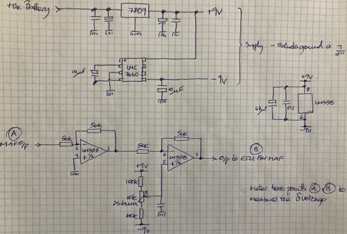
output we require. A supply of 9v works well in this regard and so I used a 7809 regulator. A second complication is the difficulty of building this circuit without using a split supply. You’ll find that if you use a single supply of ground and +9v, once the input drops below 1v, the output will start separating from the input by increasingly large amounts and no amount of adjusting will resolve the error (from 1v up, the circuit will operate reasonably well). A solution is to use a split supply which on first sight appears to be difficult but turns out to be fairly easy as Brian explained. We use the +9v to drive an LMC7660 (switched capacitor voltage converter chip in 8 pin DIL) along with two 10uF capacitors to generate a low current -9v output. Max current supplied by this device is only around 400uA but we only need around a third of that anyway - so perfect for the job.
With those two issues resolved, the design employs unity gain amps with high tolerance R’s for input and feedback and off course selected for a high impedance input and low impedance output. The first stage inverts the signal while the 2nd stage does the same and so effectively corrects it (from the point of view of the ECU). The potential divider and pot on the second stage non inverting input results in a additive voltage ranging from -0.735v to +0.845v to whatever the input is set as (the precise range is highly dependent on the exact tolerance of the R’s in the potential divider and so again high tolerance R’s work best). The 10K in the middle is a 25 turn multiturn precision pot.
On the breadboard it works like a charm but is electrically noisy as hell. Too noisy to use. First prototype PCB model is shown here sitting on the bench. The input voltage is fixed at 0.3v. The differential voltage (the difference from the output to the input) is set to +0.05v which means that the output is exactly 0.05v higher than the input and for any input from 0v to 5v. It was left on soak test for 24 hours to see if there any significant drift or alteration - none was observed. The circuit is beautifully stable and much less noisy now that it is on a prototype PCB with proper decoupling.
MAF Breadboard compensator circuit
Mass Air Flow Sensor Compensation Circuit PCB
I fitted the PCB loose inside the MAF cavity after wiring up the supply and after breaking the MAF output wiring at the socket into the two parts we need (MAF Out, ECU In). The PCB is a tight press fit inside the cavity... but really needs four dabs of araldite to fix it properly... plus an aluminium screen over the top of the case and which is earthed and silicon sealed to prevent water getting in.
I started by calibrating the new compensation unit so that the differential voltage was zero. What this means is that the adder would add zero volts to the output generated by the existing MAF and so should therefore leave the vehicle behaving exactly as it did before, with all the existing poor running symptoms of a rough, hunty idle, no oscillation around stoichiometry at idle when warm etc etc. The vehicle exhibited exactly the same faults... which is good. That means that the new circuit isn't adding any other new problem into the mix. I drove the vehicle home and with it still running adjusted the POT to slowly increase the differential voltage. Within a half turn the idle had smoothed. Oscillation of the O2 sensors started by the time I’d adjusted the pot by around a turn and a quarter. A test run followed at which point I spotted that under some conditions (deep throttle when warm) she was slightly over fueling and so I pulled into one of the car parks to back the adjustment off by a quarter turn. She then ran nicely under assorted driving conditions. When I got home, I measured the differential voltage at 0.06v. Perfect... we've effectively compensated for an under reporting MAF converting an expensive door stop into a working MAF sensor. All it took was adding 0.06v to the MAF output. This won't be the final version for three reasons. The circuit has a weakness where when the power is cut, the output fed to the ECU goes negative for a second or so and down to around -3v. There is a risk that could cause the ECU a problem long term and so I've been chatting to Brian about how I could resolve this. He suggested using a FET to control the output via a CR reset circuit which would switch the output off when the power was turned off. I'll be looking at that next. A second problem is that I've used a 47uF capacitor on the input to my 7809 voltage regulator... but when the entire system is turned off by the ignition switch, the storage that C holds causes the main ECU relay to chatter. This is easily solved with a diode but it does represent a problem that needs to be ironed out. A third issue is that instead of building this into the body of our specific MAF, I suspect it might make more sense to build this into the main wiring harness, so that any MAF could be compensated if required. Lastly, is it worth considering a mapping system to sample the MAF output digitally and if necessary remap it to any value we like and then use a DtoA to convert the remapped value to an output for the ECU? I'm pondering that right now as although I hate overkill, I do love over engineering shit. On the other hand switching to something like a megasquirt might make more sense if we're going to that much trouble. Hey ho! Thanks Brian. Seriously, what a gifted engineer you are. Comment | Back to Quick Links...