The question then was how to build a test harness?
Electrically speaking, stepper motors are not hard to rotate. It is perfectly possible to manually apply the right combinations of +12v and ground to
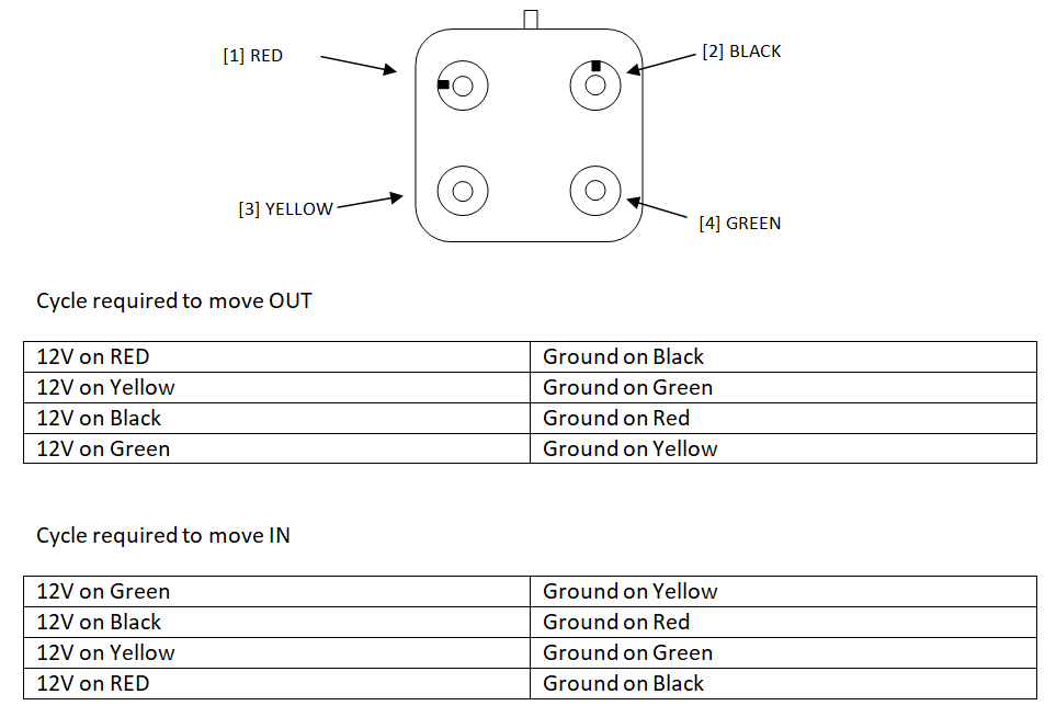
the two coils using wires and a battery and get it to move. The problem is that it takes four different combinations of voltages on the four wires to
move the stepper motor by the smallest amount either in or out - using what is called a H bridge arrangement. In practice, any significant movement
(ie: attempting to eject the shaft for cleaning) is simply too tedious to manually attempt. A far better solution would be to use a microcontroller
and as it happened, I had an old and slightly butchered PIC32MX340-512 CPU PCB hanging around the workshop. Yep, vast overkill for a project such as this
but the PCB was rough and probably wouldn't be a good choice for any new project. The 340 CPU is also a wee bit buggy... but only in terms of the
internal devices... which we actually wouldn't need for this project anyway. All we need, is a port with 10 outputs and 2 inputs. The two inputs hook
up to momentary switches for the user to select either OUT or IN movement of the stepper motor and I've written the software so that when the OUT button
is pressed, the stepper moves out by one rotation of the motor but if the button is held down, the cycle repeats reasonably quickly so the air valve plunger
moves out of the stepper in around 4 seconds. The other switch moves the plunger in (ie: into the body of the stepper motor). I used two GPIO outputs
to drive a pair of LED's as feedback for the user.
The 340 PIC chip was configured to run using its internal RC oscillator at 80Mhz and with the peripheral bus running at the same speed. Timer one was configured
to generate 1mS interrupts - which I used to monitor the state of the switches. The latency provides an easy way to debounce the switches and deal with repeat
actions when either button is held down. PIC chips are so easy to setup - they really are a joy for these types of projects.
The remaining 8 output data bits control the power to the four wires of the stepper motor.