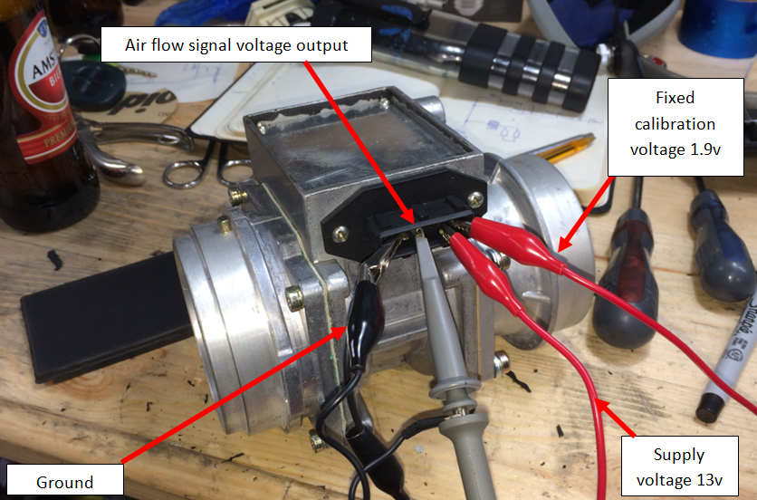
In disbelief, I took both of my MAF's onto the bench and had a closer look using the test harness shown in the picture. MAF's employ a very simple four
wire circuit. Three wires deal with the supply (ground, +12v) and the MAF air flow signal output voltage - which should sit between
0.2 and 0.7 volts with No Air Passing (what I call the NAPV - measured with plastic caps on both ends of the sensor body). A fourth wire is an input to
the MAF and is set to a value by the ECU depending on the mode the 14CUX is running in (see tune resistor). If using catalytic
converters, then this fourth wire will be 1.9v and it won't ever change. The ECU deals with this signal differently if the 14CUX is running in a different
mode from mine, at which point an adjustment screw on the side of the MAF can be used to adjust CO2.
With both my MAF units on the bench I found the following. The original MAF would generate a tiny 0.02v air flow voltage when cold but would suddenly burst
into life and start outputting around 0.4v if a hot air blower was used to heat the body of the unit up to a typical engine bay temperature. Once it had switched
into working mode, I could remove the two plastic caps, blow into the sensor and see a nice large signal swing up to around 4 volts. By contrast, the spare MAF
that I'd used right at the start as a substitution test, was completely dead and didn't generate any air flow voltage regardless of the temperature.